WATER VAPOR (H2O) ANALYZER
Cross Duct Single Gauge
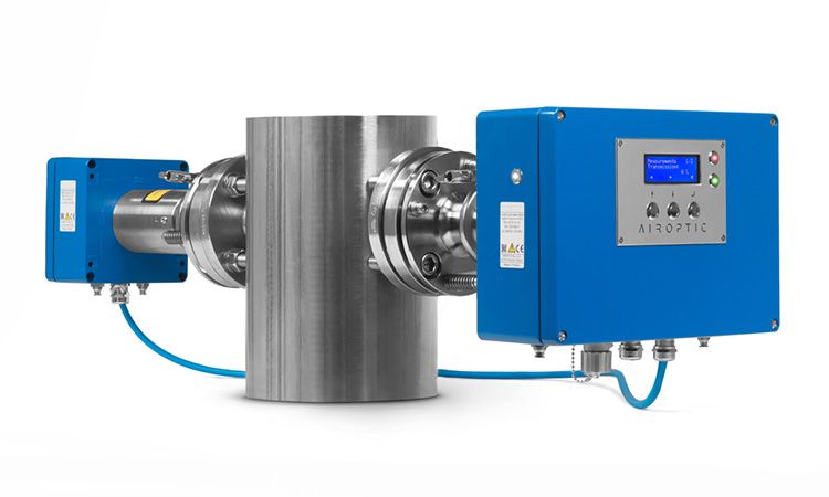
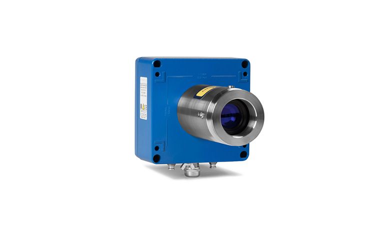
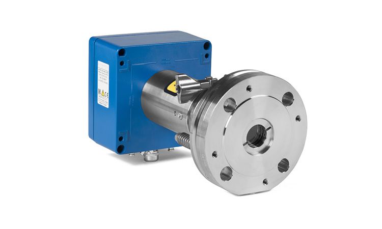
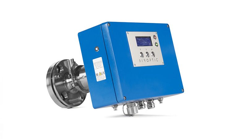
GasEye Cross Duct SG H2O
in-situ WATER VAPOR ANALYZER
GasEye H2O is a high performance in-situ water vapor analyzer. Suitable for safety applications and process control. 24/7 continuous operation. No sample preparation. No zero drift. No field calibration. Low cost of ownership.
Features
- H2O ranges: 0 – 1 ppmv / 0 – 100 vol%
- Process temperature: 0 – 1350°C
- Real time sensing: response time below 0.1 second
- High selectivity: automatic compensation for interference effect from other constituents in the gas sample
- High sensitivity: detection limit below 0.05 ppmv per meter
- In-situ monitoring: direct in the process, no sample preparation
- Maintenance free: equipped with a self-calibrating feature, no field calibration necessary
- Robustness: IP66 enclosure, suitable for outdoor and indoor installations and harsh environments
- Insensitive to dust and smoke in the measured process: up to 50 g/m3
- ATEX version available
Example Applications
- Process control
- Safety monitoring
- Gas quality measurement
Example Industries
- Petrochemical industry
- Chemical industry
- Power industry
- Steel industry
Application type
| Process gas temperature: | 0ºC to 250ºC |
| Process gas pressure: | 0.7 – 2 barA |
| Maximum path length: | up to 25 meter |
| Warm-up time: | approx. 5 minutes |
| Minimum response time (T90): | 100 milliseconds |
| Ambient temperature: | -30ºC to +55ºC |
| Ambient pressure: | 800 – 1200 hPa |
| Ambient humidity: | RH < 99%, non-condensing |
| Purging gas: | instrument air or N2 |
| Process purge flow rates: | 5 – 50 l/min |
| Sensor purge flow rates: | 0.2 – 7 l/min |
| Process gas temperature: | 0ºC to 550ºC |
| Process gas pressure: | 0.7 – 2 barA |
| Maximum path length: | up to 25 meter |
| Warm-up time: | approx. 5 minutes |
| Minimum response time (T90): | 100 milliseconds |
| Ambient temperature: | -20ºC to +55ºC |
| Ambient pressure: | 800 – 1200 hPa |
| Ambient humidity: | RH < 99%, non-condensing |
| Purging gas: | instrument air or N2 |
| Process purge flow rates: | 5 – 50 l/min |
| Sensor purge flow rates: | 0.2 – 7 l/min |
| Process gas temperature: | 250ºC – 1350 ºC |
| Process gas pressure: | 0.7 – 2 barA |
| Maximum path length: | up to 25 meter |
| Warm-up time: | approx. 5 minutes |
| Minimum response time (T90): | 100 milliseconds |
| Ambient temperature: | -30ºC to +55ºC |
| Ambient pressure: | 800 – 1200 hPa |
| Ambient humidity: | RH < 99%, non-condensing |
| Purging gas: | instrument air or N2 |
| Process purge flow rates: | 5 – 50 l/min |
| Sensor purge flow rates: | 0.2 – 7 l/min |
Technical specification
| Outputs: | 4 x analog output 4 – 20 mA (gas concentration, process transmission, 2 x AUX) – easy user selection via DIP switch between active/passive mode |
| 8 x digital output (NAMUR) | |
| Inputs: | 4 x analog input 4 – 20 mA (process temperature and pressure) – easy user selection via DIP switch between active/passive mode |
| 1 x RTD (PT100/PT1000) - easy user selection via DIP switch between PT100/PT1000 and 2-/3-/4-wires | |
| 8 x digital input | |
| Local User Interface: | Human Machine Interface (HMI) - LCD backlight display located on the transmitter housing lid |
| Ethernet port: a) WebServer – system configuration and data acquisition via web browser, b) Windows based program – GasEye logger for real-time data acquisition, c) remote service and diagnostics |
|
| Optional: | Modbus (TCP/IP), Modbus RTU, Profinet, Profibus |
| Power input: | 24 VDC nominal (19 – 30 VDC) |
| Power consumption: | < 15VA (< 25VA if ATEX) |
| Automatic gain control (AGC): | AGC ensures correct gas measurement even at high dust loads resulting in loss of optical transmission down to 0.5%. AGC operates fully automatic with no need for manual adjustment of the signal gain under any process conditions. |
| Self-calibration features: | Internal reference gas compartment is used for closed loop control of the zero and span drift |
| Download a file: | |
| GasEYE system elements: | preview |
| Active analog input: | preview |
| Active analog output: | preview |
| Passive analog input: | preview |
| Passive analog output: | preview |
| Isolated Digital Input: | preview |
| Isolated Digital Output: | preview |
| Power Supply: | preview |
| RemoteRX: | preview |
| PT100/PT1000 2-wire: | preview |
| PT100/PT1000 3-wire: | preview |
| PT100/PT1000 4-wire: | preview |
| Dimensions: | width x height: 330 mm x 230 mm, length: 350 mm |
| Weight: | 15 kg |
| Equipment: | display with status indicators, power indicator, 4 cable glands, Ethernet socket, purging fittings |
| Dimensions: | width x height: 160 mm x 160 mm, length: 330 mm |
| Weight: | 13 kg |
| Equipment: | 1 cable gland, purging fittings |
| Housings: | RAL 5010 coated aluminum, (optional RAL 7040) |
| Process interface: | stainless steel 316 with quartz window, DN50 PN16 (EN 1092-1), DN65 PN6 with easy to clean window, optional other standards (ANSI, JIS) |
| Purging tubes: | inside diameter: 38 mm, length: 400mm (optional other dimensions), stainless steel 316 (optional PTFE coating) |
| Process gaskets: | reinforced graphite |
| Download a file: | |
| GasEYE Cross Duct setup: | preview |
| GasEYE Cross Duct cross-section: | preview |
| GasEYE Cross Duct instrument assembly: | preview |
| GasEYE Cross Duct units construction elements: | preview |
| RoHS Directive 2011/65/EU | |
| Low Voltage Directive (LVD) 2014/35/EU | PN-EN 60825-1:2014-11 – Safety of laser products – Part 1: Equipment classification and requirements |
| PN-EN 61010-1:2011 – Safety requirements for electrical equipment for measurement, control and laboratory use – Part 1: General requirements | |
| Electromagnetic Compatibility Directive (EMC) 2014/30/UE | Emission: |
| EN 55016-2-1:2014+A1:2017 – Measurements of conducted disturbances emission | |
| EN 55016-2-3:2017+A1:2019 – Measurements of radiated disturbances emission | |
| Immunity: | |
| EN 61000-4-2:2009 – Electrostatic discharge immunity | |
| EN 61000-4-3:2006 + A1:2008 + A2:2010 – Radiated, electromagnetic field immunity | |
| EN 61000-4-4:2012 – Electrical fast transient / burst immunity | |
| EN 61000-4-5:2014 + A1:2017 – Surge immunity | |
| EN 61000-4-6:2014 – Immunity to conducted disturbances | |
| EN 61000-4-29:2000 – Immunity to voltage dips, short interruptions and voltage variations | |
| ATEX Directive 2014/34/EU | EN IEC 60079-0:2018 - Explosive atmospheres - Part 0: Equipment - General requirements |
| EN 60079-2:2014 - Explosive atmospheres - Part 2: Equipment protection by pressurized enclosure "p" | |
| EN 60079-11:2012 - Explosive atmospheres - Part 11: Equipment protection by intrinsic safety "i" | |
| EN 60079-26:2015 - Explosive atmospheres - Part 26: Equipment with Equipment Protection Level (EPL) Ga | |
| EN 60079-28:2015 - Explosive atmospheres - Part 28: Protection of equipment and transmission systems using optical radiation | |
Explosion protection (standard version):
|
|
| Explosion protection - ATEX Zone 1/21 (optional version): GasEye Cross Duct Ex1:
GasEye Cross Duct Ex1 IS:
GasEye Cross Duct Ex1 ET and GasEye Cross Duct Ex1 ET IS:
Certificate No. KDB 20ATEX0003X EN |
|
Explosion protection - IECEx Zone 2/22 (optional version):
|
